Knowledge Base

Getting Started

Configuring NP-View Server

Getting Started

Once NP-View Server is installed, the application will start automatically. Note that NP-Live has been Rebranded to NP-View Server.  Several of the instructions still correctly refer to NP-Live as we migrate the installation services to the new product names.

If the Linux Administrator wishes to start and stop the application, two helper scripts have been included to aid in these tasks:

  • Stop : sudo /opt/np-live/stop_NP-Live.sh
  • Start : sudo /opt/np-live/start_NP-Live.sh

NP-View Docker IP Conflict

+
If NP-View Docker is using IP addresses that conflict with addresses used on the local area network, the IP addresses used by Docker can be changed as follows:

Create a docker network with the subnet you would like to use:
sudo docker network create --driver overlay --subnet x.x.x.x/x NP-Live_external

Navigate to the np-live install directory (default /opt/np-live):
cd /opt/np-live

Add the following config to local-settings.yml (tab indented to reflect table below):
networks:    
  NP-Live_external:  
    external: true

Replace all instances of the default network in docker-compose.yml to NP-Live_external:
sudo sed -i 's/- default$/- NP-Live_external/g' docker-compose.yml

Stop and start the app:
sudo sh ./stop_NP-live.sh && sudo sh ./start_NP-live.sh

#Note: docker commands (and the start/stop NP-live scripts) will require sudo unless you are the root user or your user is part of the docker group

Version mismatched between two compose files : 3.4 and 3.1

+
When starting NP-View Server, if this error is received, the version number in /opt/np-live/local-settings.yml needs to be at “version: ‘3.4’”. If not at version 3.4, please replace the contents of the local-settings.yml file with the code listed in the Setting the NP-Live Virtual Appliance Time Zone section and set your application time zone accordingly. This file is sticky and will remain after future upgrades. After the update, start the server using the above command.

Upon initial start, the Welcome screen shows the configuration wizard to guide the Administrator through the remaining configuration steps which include:

  1. Authentication
  2. Licensing
  3. Users

Configure Authentication

The following authentication options are available to configure in NP-View Server.

  • Active Directory / LDAP
  • Radius
  • Local

Active Directory or LDAP

For Active Directory or LDAP authentication we use LDAPv3 TLS over port 389.  If the communication returns an exception, we attempt unencrypted communication. We do not support LDAPS.  Before starting, note that setup requires a dedicated Credential Binding Account (LDAP Administrator). The Credentials Binding Account must be included in at least one of the system groups for NP-View Server to query and link the users.

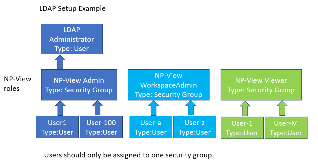
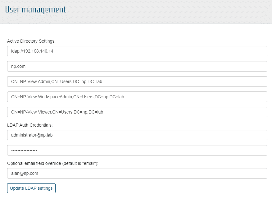
An example of a properly configured LDAP screen on NP-View is below:

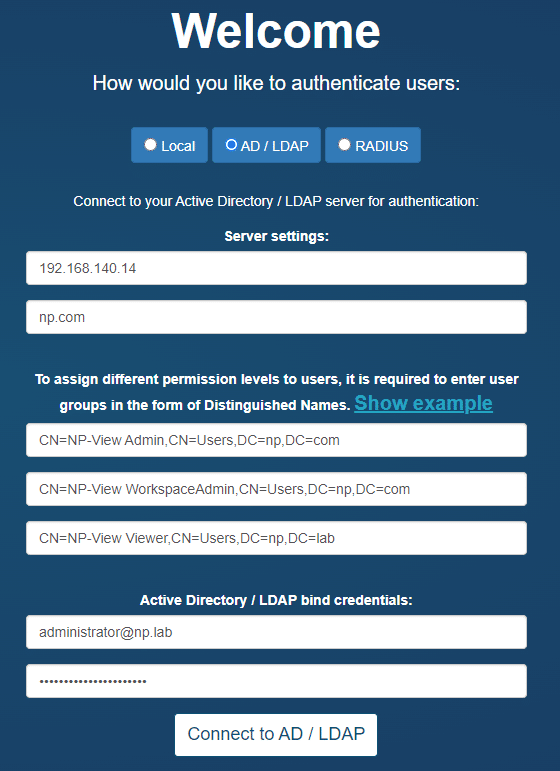
The setup page will allow for the definition of three system groups using a Distinguished Name.  A Distinguished Name (often referred to as a DN or FDN) is a string that uniquely identifies an entry in the Directory Information Tree. The format of a DN is: CN=groupname,OU=grouptype,DC=subdomain,DC=example,DC=com.  Your domain needs to match the DC specified in your DN. For an example DN like above, the domain would be: ‘subdomain.example.com’.

For example:

ldap_group_admin = 'CN=NP-Live Admin, OU=Permissions, DC=ad, DC=np, DC=test'
ldap_group_write = 'CN=NP-Live WorkspaceAdmin, OU=Permissions, DC=ad, DC=np, DC=test'
ldap_group_read = 'CN=NP-Live Viewer, OU=Permissions, DC=ad, DC=np, DC=test'

group_translation = {'Administrator' : ldap_group_admin,
'WorkspaceAdmin' : ldap_group_write,
'Viewer' : ldap_group_read}

Reminder:   The three CN names must be unique or roles will be overlapped in NP-View resulting in features being disabled.

To find the DN on Windows, open a Windows command prompt on your Active Directory server and type the command: dsquery group -name "known group name".

Users assigned to NP-View must login once to get setup within the NP-View database for sharing and transferring of workspaces.  No users exist until after the first login.

Troubleshooting Active Directory Setup

If an error is returned when configuring Active Directory, the steps to troubleshoot are:

Step 1: From your Active Directory server, type the command below in a terminal after replacing the “CN=…” portion with the Distinguished Name of the group you’d like to check:

dsget group "CN=groupname,OU=grouptype,DC=subdomain,DC=example,DC=com" -members

Verify that the output shows the expected list of user(s) in that group. If it doesn’t, check your Active Directory group and user configuration.

Step 2: From your Active Directory server, type the command below in a terminal after replacing the “CN=…” portion with the Distinguished Name of the group you’d like to check, and also replacing USERNAME with your actual username:

dsquery * -Filter "(&(objectClass=user)(memberOf:1.2.840.113556.1.4.1941:=CN=groupname,OU=grouptype,DC=subdomain,DC=example,DC=com)(sAMAccountName=USERNAME))"

If the output is empty, verify that your user in Active Directory has the attribute sAMAccountName set. If not, set it and try the command again. Verify also that the sAMAccountName value matches your AD username value. You can also try to enter the username in the NP-View Active Directory configuration form with the format USERNAME@DOMAIN.

If the output shows the expected list of groups for that user, but NP-View still generates an error, then contact the NP support team.

Radius

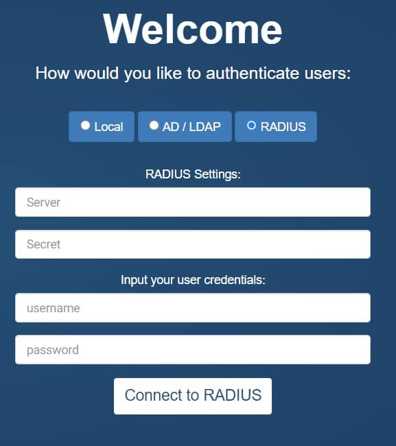
Radius authentication requires your server address and secret. Once input, the user can test their connection using their personal login credentials for verification.  Note that for Radius authentication, all users are assigned to the Administrator group.

Welcome: How would you like to authenticate users

Local Authentication

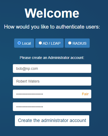
NP-View Server provides an internal mechanism for the administration of users.  During setup, the screen will require the user to setup the Administration account by inputting a user ID and password.  This account will be assigned to the Administrator role and will have access to all system features. An example of a properly configured Local Auth screen on NP-View is below:
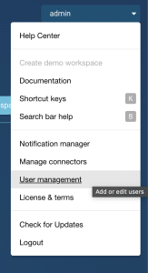
User Management

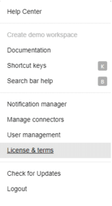
NP-View Server provides a User Management function for users assigned to the the Administrator role. It can be accessed in the user menu at the top right of the screen either on the workspace page or from within a workspace.

User Management – Active Directory or LDAP

Clicking User Management will open a window that shows the LDAP setup information. The left half of the screen allows the user to change the NP-View LDAP settings.  LDAP Auth credentials are required to update the information.  The optional email field override is used as the default email address for the Notification Manager if no email address is provided as part of the LDAP credentials.

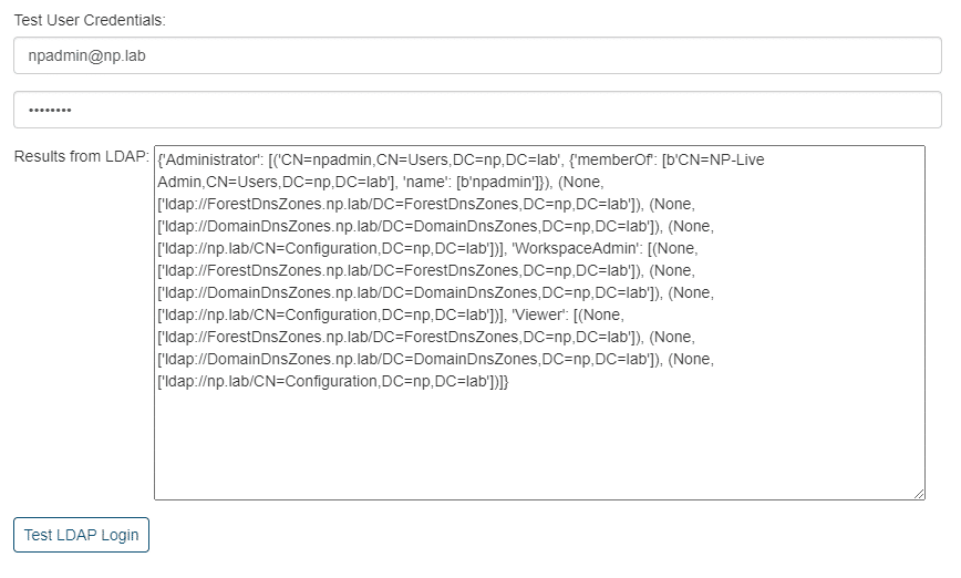
The right half of the user management screen allows for the testing of each LDAP user and will retrieve their LDAP settings for review.

User Management – Local Authentication

Clicking User Management will open a window that shows the user related information associated with this account, their account details, and their account permissions.

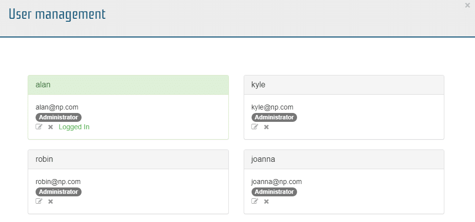
From this window Administrators can edit (pencil icon), delete (x icon) or add user accounts (create new user button).

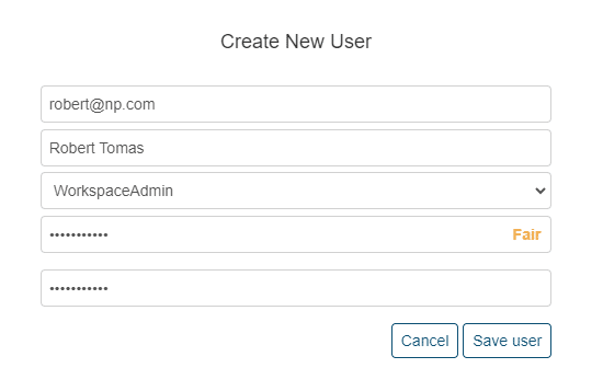
A user’s ID should be the user’s email address (this will be used for notifications) and an administrator-defined password.  Each user will need to be assigned to a role which will provide the user with system wide access.

  1. Administrator – Has access to all users, workspace and system administration functions including managing users and license functions.
  2. WorkspaceAdmin – Has access to all workspace administration functions.
  3. Viewer – Has read only access to the system.

Reset Authentication

The Administrator can also reset the authentication method entirely by selecting the “Reset authentication system” link. “Reset authentication” only resets the authentication and does not remove any workspaces or data.  Note that workspaces are assigned to user id’s.  If the authentication method (or user id format) is changed, the workspaces will no longer be available to users.  The administrator or workspace admin must utilize the transfer workspace function to assign the legacy workspace to the new user id’s.

Password Reset

  • Workspace Admin or Viewer user groups:  Contact your Administrator who can manually reset your password through the User Management function on the system menu (upper right corner).
  • Admins: connect through SSH to the NP-View server and remove the file db/auth_provider.cfg inside the NP-View application folder (by default: /opt/np-live).
  • Refresh the NP-View web page to show the Welcome screen and reconfigure the authentication.

License and Terms

The Administrator can Show, Upgrade or Renew their license. Licensing terms and legal disclosures are available from the system menu where user management is found.

Configure License Key

After the authentication, the Welcome screen will guide the Administrator through reviewing the EULA and adding the license key. The license key should have been sent to you by email and also posted on the Network Perception portal. If you haven’t received a key, please send a request to support@network-perception.com. Renewed or upgraded license keys can only be installed from the home screen (not from within a workspace) by members of the Administrator group.

Additional Configuration Features

Configure Automatic Updates

NP-View Server can automatically download new releases and update itself if you select “Automatically check for updates”.  Alternatively, you can select “Update NP-View” from the upper right menu or update offline using the following steps:

  1. Download the latest release from the Network Perception portal.
  2. Copy the release file to the NP-View Server using SCP or WinSCP
  3. Connect to the NP-View Server shell using SSH and execute the release file with the command sudo sh NP-View_server_installer.sh

Configure Shutdown and Startup Options

To speed performance on startup, NP-View terminates background processes that are running when the system is gracefully shutdown and clears out all tasks and jobs.  If any processes remain upon startup, they are also terminated. To change the configuration,

  • stop the NP-View Server application.
  • in the docker-compose.yml file for the manager change cancelTasksStartup=True to cancelTasksStartup=False
  • in the docker-compose.yml file for the manager change clearRqStartup=True to clearRqStartup=False Note that the previous setting must also be set to True for this operation to work.
  • start the NP-View Server application.

Configure User Timeout

The system can be configured automatically time out a user after a period of idle days.  The default is set to 30 days. To change the configuration,

  • stop the NP-View Server application.
  • in the docker-compose.yml file for the webserver\environment service, change sessionLengthDays=30 to any positive floating point number representing elapsed days. For Example:
    • 0.5 = 12 hrs
    • 1.5 = 36 hours
    • 30 = 720 hrs.
    • If set to 0, user timeout will default to 30 minutes.
  • start the NP-View Server application.

Timeout for connectors is 1 day and cannot be changed. Also, the timeout value is not static and will be overwritten by the next software update. Prior to restarting after an update, the timeout needs to be reset to the value of choice.

Configure Devices within a Custom View

The system can be configured to allow for more devices within a custom view.  The default is set to 25 devices. To change the configuration:

  • stop the NP-View Server application.
  • in the docker-compose.yml file for the
    • services : manager : environment, change devCountLimit=25 to a positive integer.
    • services : bgmanager : environment, change devCountLimit=25 to a positive integer.
    • services : webserver : environment, change devCountLimit=25 to a positive integer.
  • start the NP-View Server application.

Note: The limit is not static and will be overwritten by the next software update. Prior to restarting after an update, the limit needs to be reset to the value of choice. Note: NP has only tested the system to the default limit. Raising the limit is at the user’s risk as unintended consequences including data loss and the system exhausting system resources may occur.

Configure A Static IP Address on your Linux Server

To set a static IP address for your NP-View Server, follow the instructions in this document.

Updating NP-View Server

This section describes how to update the NP-View Server application and the underlying components if the OVF was used for the initial installation.

Updating the NP-View Server Application

To update an existing NP-View Application, the steps are:

  1. Download the latest release Linux Installer Release (not the .OVF) from the Network Perception Portal and copy it onto your NP-view server using SCP (or WinSCP from a Windows client)
  2. Login onto the NP-View server using SSH (or Putty from a Windows client)
  3. Get root permissions using the command: sudo -i
  4. Prior to installing the new version, it is recommended to make a backup of your database (see below)
  5. Execute the new NP-View release file using the command: sh NP-View_installer.sh  (where NP-View_installer.sh is the name of the new release file downloaded in step 1).
  6. Follow the guided steps of the installer, which will automatically start NP-View once the update is complete.
  7. Connect to the user interface of NP-View using your web browser and check in the bottom-left corner of the home page that the version number matches the new release

Get Version API call

To check the version update your server URL to the following

https://<np-view_server_address>/version

Backing up the NP-View Server Database

  1. Stop the NP-View Server (you can use the script /opt/np-live/stop_nplive.sh)
  2. From the NP-View Server folder (by default: /opt/np-live/, run the command: tar -zcf db_backup_$(date '+%Y_%m_%d').tgz db (this command may take few minutes to complete)
  3. Run the new release installer, which will update the containers and then launch NP-View Server

Updating CentOS 7 and Docker

If the OVF was used for the initial installation, that package included the CentOS 7 operating system and Docker. These applications must be updated separately from the NP-View Server Application using the below instructions. The instructions cover NP-View Servers that have internet access and those that do not have internet access.

CentOS will be EOL June 30, 2024. We recommend customers to transition to Ubuntu. Our new OVF uses Ubuntu and instructions for updating Ubuntu will be coming soon.

Updating when the NP-View server has internet access:

– stop NP-View
cd /opt/np-live/
./stop_NP-Live.sh

– run all updates
yum update -y

– reboot server
reboot

Updating when the NP-View server does not have internet access:

If NP-View server is installed in an environment that does not have internet access, a separate Centos 7 server with Docker that has internet access is required to create the update package. All commands below are case sensitive.

Network-Perception uses this mirror for CentOS updates and this mirror for Docker updates

Centos 7 that is online:

– make sure you are root
sudo su -

– create packages directory
cd /root/
mkdir packages
cd packages

– download all packages
yum list installed | awk {'print $1; }' | tail -n +3 | xargs yumdownloader

– you should see docker included in the output list.

– compress archive (capital -C is important)
tar czf /root/packages.tar.gz *.rpm -C /root/packages/

– Copy packages.tar.gz to the offline server. The user can use the below command to scp:
scp packages.tar.gz root@ipAddress:/root/

Centos 7 that is offline running NP-View:

– make sure you are root
sudo su -
– stop NP-View
cd /opt/np-live/
./stop_NP-Live.sh

– create directory and extract the archive
cd /root/
mkdir packages/
mv packages.tar.gz packages/
cd packages/
tar -xf packages.tar.gz

– install all updates:
yum -y localinstall *.rpm

– reboot server
reboot

– now everything is up to date on the offline server.

If you get any docker swarm errors:

– make sure you are root
sudo su -

– leave and join swarm cluster
docker swarm leave --force && docker swarm init

Product Tutorials

1. Network Mapping

Network mapping provides the Networking Team (Network Engineer, Network Security) with capabilities that allow users to:

  • Visualize an accurate topology of the network architecture
  • Identify and label critical cyber assets and critical network zones
  • Easily review which devices are protecting which network zones

Visualize Topology

NP-View can be used to discover your network topology and the underlying control plane, including layer-2 and layer-3 configurations. Without leaving the topology map, you can review many aspects of the network’s design including Firewalls, Routers, Switches, Gateways, Networks, VPNs, Hosts and more.

Critical Assets and Zones

Each asset can be tagged with categories and criticalities as well as grouped into zones making it easy to review which devices are protecting which network zones.

Details On-demand

Selecting a node in the topology map will interactively display an information panel with detailed data about that node.

2. Firewall Ruleset Review

Firewall ruleset review provides Network Engineers, Network Security, and Compliance Analysts with functionality for:

  • Easy review of firewall access rules and object groups using the Access Rules and Object Groups reports.
  • Automatic identification of configuration risks using the Risks and Warnings report.
  • Validating recent policy modifications as part of a configuration change review process using the Change Tracking report.

How to Review Access Rules

An independent review of firewall policies has to be periodically conducted to ensure that network access rules are correctly implemented and documented. It is important because lack of access rule review leads to unexpected network access vulnerabilities.

  • Frequency: each time firewall policies are changed, and at least once a quarter
  • How to do it:
    • Step 1: given a workspace populated with network device configurations, open the Access Rule table from the main menu (top left)
    • Step 2: leverage the “Column Search” feature or the “Compare” feature to show the rules in scope of your verification
      • For instance, filter the “Device” column to only show rules for a specific device, or filter the “Binding (ACL)” column to only show rules bound to a specific interface, or use the “Compare” feature to only show rules added or removed recently
    • Step 3: review values for the source, destination, service, binding, risk, and description of each rule in scope
      • The “Description” column captures comment, description, or justification from the device configuration
      • The “Risk” and “Risk Criticality” columns are populated by NP-View during the automated risk analysis
    • Step 4: to identify rules that are not justified, sort the table by “Description”. Empty values will be shown at the bottom.
    • Step 5: to document your review process, double click on the “Comment” or “Comment Status” cells to add your own comment. The comment status can be either “Verified” or “To Review” or “To Revise”
    • Step 6: to save an evidence of your review process, export the table to Excel using the export options in the top right corner of the table

Access Rules Table

The Access Rules report provides the users with complete details on each Access Rule with the ability to add justifications and actions.

Object Groups

The Object Groups report provides the users with complete details on each Object Group with the ability to add justifications and actions.

Risks and Warnings

As modifications are made to the network, the Network Perception default Policies and Requirements identify potential risks.  The Risks and Warnings report provides the users with a summary of the potential risks and their criticality with the ability to add actions and comments.

Change Tracking

As modifications are made to the network and the updated configuration files are imported, the changes are logged in the Change Tracking table.

tracking table
3. Segmentation Verification

Segmentation verification provides the Networking Team and Audit Team with capabilities that allows users to:

  • Assess correctness of network segmentation
  • Identify risky network connectivity paths
  • Understand exposure of vulnerable assets

Network Segmentation Accuracy

NP-View be used to verify the accuracy of your network segmentation.

The connectivity matrix which is available from the device info panel can be used to verify open ports between devices.

Inbound and outbound connections can be verified for each network using the highlight paths function.

Identifying Risky Connectivity Paths

Using industry best practices, Network Perception automatically identifies potential risks related to network configurations. Using the Network Perception  Connectivity Path analysis, the user can review each of the highlighted risks and make a judgment on action.

organization table

Exposure of Vulnerable Assets – Vulnerability Analytics

NP-View provides your security team with a single pane of glass for reviewing network vulnerability exposure. With the addition of scanner data or data from a vulnerability data service, vulnerabilities can be tracked across your network.

Topology Display of Vulnerabilities

When scanned data has been added to a workspace, and a topology view is built that also includes that scan data, nodes on the topology of that view will be marked with a shield indicating the presence of vulnerabilities.

These shields can be toggled on and off using the topology settings menu.

Device Panel Display of Vulnerabilities

Firewalls, Gateways, and Hosts may contain vulnerability and service information imported from scans. Clicking on any of these nodes in a View that contains vulnerability information, will display it in the info panel that opens over the main menu.

Clicking on the Vulnerabilities link will present a pop out with the vulnerability details.

Audit Assistance

Performing a regular review of your compliance metrics is important for your organization.  Performing the review manually is time consuming and tedious. Audit assistance provides the Compliance Team (Auditor, Compliance Officer, Compliance Analyst, and Consultants) with capabilities that allow users to:

  • Verify compliance with cybersecurity regulations and best practices through Policy Review.
  • Seamlessly store evidence for compliance review with Change Tracking.
  • Easily prepare compliance reports using the Audit Assistants listed below:

Workspace Report (Standard)

The Workspace Report assistant is available within each workspace and will generate a report for a specific view that includes detailed information about configuration files that were imported and parsed including:

  • Configuration assessment report including risk alerts
  • Ports and Interfaces
  • Access rules
  • Object groups
  • Path analysis

Industry Best Practice (Premium)

The Best Practice assistant requires a license to activate. This report is available within each workspace to generate a report for a specific view that includes the following topics:

  • Parser Warnings and potential misconfigurations
  • Unused Object Groups
  • Access Rules missing a justification
  • Unnamed nodes
  • NP Best Practice Policies on access rules and CiS Benchmarks that have identified potential risks
  • ACL’s with no explicit deny by default rule

NERC CIP Compliance (Premium)

The NERC CIP assistant requires a license to activate this function and guides the user through the steps required to create a report covering CIP-005 requirements. The NERC CIP audit assistant is only available within a NERC-CIP workspace and allows audit teams to classify BES cyber assets as High, Medium, and Low based on the standards. We have added a category for untrusted (Internet, Corp, etc.) to tag non BES assets. NP-View allows compliance teams to collect and report evidence related to the following requirements:

  • CIP-002 – BES Cyber System Categorization; impact rating and 15-month review
  • CIP-003 – Security Management Control; cyber security policy
  • CIP-005 – Electronic Security Perimeter; remote access management
  • CIP-007 – System Security Management; ports and services
  • CIP-010 – Change Management and Vulnerability; configuration change management, configuration monitoring, vulnerability assessment

A demo workspace for the NERC CIP audit assistant is included with the software.  To see the audit assistant in action, follow these steps:

  1. Click on the demo workspace to build the topology.
  2. Create a custom view by selecting all of the firewalls, right click, Create View from Selection and give it a name.
  3. Once the view is generated, select Manage Zones from the left manu and click on the Auto Generate Zones button.
    • Red zones represent your high criticality assets.
    • Orange zones represent your medium criticality assets.
    • Yellow zones represent your low criticality assets.
    • Gray zones represent your untrusted assets.
  4. On the left menu, select Summary Reports and the NERC-CIP Compliance Report
  5. Click through the wizard, the defaults will represent the selections suggested by the auto group function.
  6. Click Generate Report to view the report in a new tab.

Feature Documentation

Connectivity Matrix

The Connectivity Matrix illustrates port access between devices and interfaces.  This allows users to analyze and confirm communication between interfaces.

Each row or column header cell contains four pieces of information.

  • Interface Name
  • Alias
  • IP Address
  • Security Zone

Each cell will contain connectivity information

  • Red pill: Denied – No access
  • White pill: IP, TCP, UDP/Any – open access
  • Green pill: Port specific access

The Connectivity Matrix is accessible from the device Info panel

Saving the Matrix

Two paths to save and document The Connectivity Matrix for your organization to use as an artifact:

  • Copy and Paste directly into Excel or Sheets
  • Step 1
    • Create the connectivity matrix
  • Step 2
    • Copy all cells directly to Excel
  • Or
  • Take a screenshot

Connectivity Paths Report

This article will focus on the Connectivity Paths Report.

NP-View uses reports to present network information related to the open workspace.  These reports are available to all users and can be accessed from the main menu. For more information visit the Workspace Reports Overview article.

Connectivity Paths

This report provides a summary of network paths and their analysis results. Connectivity paths are created during the analyze process and are only available within a view. See this article for an overview of views.

The connectivity paths table provides a detailed explanation of the flow of information through the topology.  It describes the source and source node, destination and destination node, as well as the port, protocol and service.  The rue sequence traverses the access rules used to complete the path and the path sequence is the sequence of hops the path takes.

By clicking on a specific rule sequence from within the + box, the associated access rule can be displayed for review and comment.

Connectivity Paths Columns

  • Destination: (PATH_DST_IP_BEGIN : PATH_DST_IP_END) IP address range of the destination
  • Destination Node: (PATH_DST_NODES) device name or IP address of the destination node
  • Path Number: internally generated value used as a marker for each path.
  • Path Sequence: (PATH_SEQUENCE) List of IP address or devices traversed by the path from source to destination.
  • Port: (PATH_SRC_PORT_BEGIN ) The port that is open along the path
  • Protocol: (PATH_PROTOCOL) The protocol enabled on the path
  • Rule Sequence: (PATH_RULE_SEQUENCE) Access list sequence of rules and reference line number within the configuration file
  • Service: (PATH_SERVICE) The service that corresponds to the open port.
  • Source: (PATH_SRC_IP_BEGIN : PATH_SRC_IP_END) IP address range of the source
  • Source Node: (PATH_SRC_NODES) device name or IP address of the source node
Compare Path History

Compare path history

This interactive report, accessible from the main menu, provides a network path comparison between two points in time.

When a configuration file is added to the system and is different from the previously imported file, a new “Version” is created.

The user can select two versions to compare.  The resulting table will display the changes between the two files. Removals are shown in the left column and additions are shown in the right column.

*Compare Path History 0pen and two versions selected

*Closeup on the comparison results

Export Map

Export Map

NP-View provides the ability to save a copy of the current Topology Map for record retention as:

  • PDF
  • Visio Diagram

Export Map can be accessed from the main menu.

A dialog will open where you can choose the type of Export.

Example of PDF export displaying

  • Workspace Name
  • View
  • Date of Export

Map exports can also be included in a NERC-CIP summary report using the NERC wizard.

Example of a Visio export

Supported Devices & Data

Firewalls, Routers, Switches

The following table is a comprehensive list of supported devices. The instructions provided in the table can be used to manually extract data from the device for import. While we do our best to support the below devices, it is impossible for us to test the parsers with every possible device configuration combination. If errors occur during device import, Network Perception is committed to working with our customers to resolve their specific parsing issues.

Note that Network Perceptions device support policy follows that of the manufacturer.  When a manufacturer ends support for a product, so does Network Perception.  End of support devices are not removed from NP-View but will not be upgraded if issues arise.

Supported Devices with Vendor Partnership

The devices in this list are actively tested in our lab to support the most current versions of the manufacturer software. Network Perception has an active partnership with these vendors for software and support.

Vendor Type/Model/OS Configuration files needed
Check Point R81 / R81.10 / R81.20 including Multi-Domain Security and Virtual Router support (VRF) We support the database loading using the NP Check Point R80 Exporter (PDF documentation, video). Zip File Shasum: 5d22b182d773c020fd2a58838498b8be8221468e Exporter Tool Shasum: cc3131da37362da1291fa4a77cd8496fcb010596
Cisco
  • ASA Firewall (9.8 and up) including multi-context and Virtual Router Forwarding (VRF).
  • FTD Firewall (7.1.x, 7.2.x)
  • IOS Switch (15.7 and up) including Virtual Router Forwarding (VRF).
  • ISR (IOS-XE 17.6.x and up)
  • We do not support Application Centric Infrastructure (ACI) or NX-OS
For a Cisco IOS device, the sequence would be:
  • enable (to log into enable mode)
  • terminal length 0 (it eliminates the message between screens)
  • show running-config
For a Cisco ASA, the sequence would be:
  • enable
  • terminal pager 0
  • show running-config
For FTD, see additional instructions below
Fortinet FortiGate Firewall, FortiSwitch (FortiOS 7.0.x, 7.2.x) To get a config capture from the CLI using Putty (or some similar SSH) client, here is the process:
  • Turn on logging of the CLI session to a file
  • In the CLI of the FortiGate, issue these commands in sequence:
  • config system console
  • set output standard
  • end
  • show full-configuration
  • Turn off logging
Palo Alto Next Gen Firewall (PanOS 10.x, 11.x) including multiple virtual firewalls (vsys) and virtual routers (vrf). We do not support SD-WAN See additional instructions below

Supported Devices with no Vendor Partnership

The devices in this list are actively tested in our lab to support the most current versions of the manufacturer software.

Vendor Type/Model/OS Configuration files needed
Dell – SonicWall SonicOS (5.9.x, 6.5.x) “From GUI, Go to Export Settings, then Export (default file name: sonicwall.exp)” see additional instructions below
FS Switch (FSOS S5800 Series; Version 7.4) show running-config Note that FS configs are Cisco like and not tagged specifically as FS so these switches will display as Cisco devices in NP-View
pfSense Community Edition 2.7.2 Diagnostics > Backup & Restore > Download configuration as XML
Schweitzer Ethernet Security Gateway (SEL-3620) SEL Firmware: from “Diagnostics”, click on “Update Diagnostics” and copy the text OPNsense: from ‘System > Configuration > Backup’ export .XML backup file Note: IPTables from OPNsense are not supported in NP-View.
Siemens – RUGGEDCCOM ROX Firewall RX1000-RX5000 (2.x) admin > save-fullconfiguration. Choose format “cli” and indicate file name

Historical Devices

The devices in this list were developed based on customer provided configuration files.  We are no longer actively developing these parsers but they are supported for break/fix and require customers sanitized config files to assist with the debug of issues.

Vendor Type/Model/OS Configuration files needed
Dell PowerConnect Switch console#copy running-config startup-config (instructions)
Nokia Service Router (SR7755; TiMOS-C-12.0.Rx) admin# save ftp://test:test@192.168.x.xx/./1.cfg
↳Alcatel-Lucent Service Aggregation Router (SAR7705; TiMOS-B-8.0.R10) admin# save ftp://test:test@192.168.x.xx/./1.cfg
Berkeley Software Distribution (BSD) Firewall (Open, Free and Net; 3 series) ifconfig -a > hostname_interfaces.txt See additional instructions below
Extreme Switch (x400, x600; XOC 22.6) save configuration
Hirschmann Eagle One Firewall (One-05.3.02) copy config running-config nv [profile_name]
HP / Aruba ProCurve Switch (2600, 2800, 4100, 6108) show running-config
NetScreen Firewall (ISG, SSG) get config all
Juniper Junos Firewall SRX-V (20.x) NetScreen Firewall (ISG, SSG) For JunOS, the command should be:
  • show configuration | no-more
For Juniper ScreenOS, the sequence is:
  • set console (N would be the number of expected lines like 1000)
  • get config all
Linux BSD IP Tables Firewall iptables-save See additional instructions below
NETGEAR Smart managed Pro Switch (FS/GS-Series; 6.x) CLI: show running-config all Web UI: Maintenance > Download Configuration
Siemens ROS Switch (RSG2-300; 4.2) config.csv
↳Scalance X300-400 Switch cfgsave
Sophos Firewall (v16) Admin console: System > Backup & Firmware > Import Export
VMware NSX Firewall GET https://{nsxmgr-ip}/api/4.0/edges/ (XML format) Learn more about vCenter and VSX
WatchGuard Firewall (XTM 3300, XTM 850) Select Manage System > Import/Export Configuration

Additional Instructions

Collecting Data from the Device Console

+

Collecting configuration information from the device console can be an easy way to get the device data.

Following the below rules will help ensure success when importing the files into NP-View.

Note that not all data can be retrieved from the console. Please review the section for you specific device for additional instructions.

  1. Run the command from the console.
  2. Copy the text to a plain text editor. Do not use Word or any fancy text editor as it will inject special characters that we cannot read.
  3. Review the file and look for non text characters like percent encoded text or wingdings like characters. These will break the parser.
  4. Save the output of each command in a separate file and name it after the device so that NP-View can properly attribute the files. For example: firewall1_config.txt, firewall1_arp.txt, firewall1_route.txt
  5. For Palo Alto files, there are specific naming requirements, please see the Palo Alto section for additional information.
  6. Some config files contain very long strings. Line wrapping due to the window size of the terminal will break the parser. If using a terminal like Putty, please ensure the terminal is set to maximum width.
config system console
set output standard
end

Finally, if you encounter a parsing error when loading the files and want to upload the files to Network Perception using the portal, please sanitize all files at the same time so that we can keep the data synchroized across the files.

Berkeley Software Distribution (BSD)

+

BSD has three firewalls built into the base system: PF, IPFW, and IPFILTER, also known as IPF FreeBSD

  • Packet Filtering (PF): Rules located in file /etc/pf.conf
  • IP Firewall (IPFW): Default rules are found in /etc/rc.firewall. Custom firewall rules in any file provided through # sysrc firewall_script=”/etc/ipfw.rules”
  • IP Filter also known as IPF: cross-platform, open source firewall which has been ported to several operating systems, including FreeBSD, NetBSD, OpenBSD, and Solaris™. Name of the ruleset file given via command ipf -Fa -f /etc/ipf.rules

OpenBSD

NetBSD

BSD and similar systems (e.g., Linux) will use the same names for interfaces (eth1, eth2, em1, em2, carp1, carp2, etc.). The parser might be confused if the user imports interface files and packet filter configs from different systems at the same time resulting in a combined system instead of individual devices. To prevent this, the user should group all files by host, making sure to name the ifconfig file after the hostname (i.e. host1_interfaces.txt).

Free BSD Example

Below is an example of a 2 host FREE BSD system containing FW1, host1 and host2. The user should import the files in each section as a separate import. fw1 – first data set import (all available files imported together)

  • pf.conf (required file) (note, can be named differently, e.g., FW1.txt’)
  • obsd_fw1_interfaces.txt (required file) (note that the parser keys on the “_interfaces” string”. Text before “_interfaces” will be used to name the device. In tis example ‘obsd_fw1’)
  • hostname.carp1
  • hostname.carp2
  • hostname.hvm2
  • hostname.hvm3
  • hostname.hvm4
  • table1
  • table2

host1 – second data set import (all available files imported together)

  • pf.conf (required file) (note, can be named differently, e.g., host1.txt’)
  • host1_interfaces.txt (required file) (note that the parser keys on the “_interfaces” string”. Text before “_interfaces” will be used to name the device. In this example ‘host1’)
  • hostname.em1
  • hostname.carp1

host2 – third data set import (all available files imported together)

  • pf.conf (required file) (note, can be named differently, e.g., Host2.txt’)
  • host2_interfaces.txt (required file) (note that the parser keys on the “_interfaces” string”. Text before “_interfaces” will be used to name the device. In this example ‘host2’)
  • table1
  • table2

The only required files are the config file (can be named something other than pf.conf) and the ifconfig file. hostname files are optional (unless they contain description of interfaces not in the ifconfig file). Table files contain a list of IP addresses that can be manipulated without reloading the entire rule set. Table files are only needed if tables are used inside the config file. For example, table persist { 198.51.100.0/27, !198.51.100.5 }

Legacy Fortinet Support

+

Support for Fortinet through 6.2 ended September 2023. Please note that no upgrades to these parsers will be made.

Palo Alto Panorama & NGFW

+

Panorama

If Panorama is used to centrally manage policies, the access rules and object groups can be retrieved from these devices in XML format (we do not support the import of unstructured text files). If using the Panorama connector, the required files will automatically be downloaded:through 6.2 ended September 2023. Please note that no upgrades to these parsers will be made.

The Panorama file will only contain centrally managed access rules and object groups.

Locally defined access rules and object groups cannot be retrieved from Panorama and must be retrieved from each NGFW. Please follow the instructions below to export directly from the Next Gen FireWall using API.

Palo Alto Firewalls will ALWAYS have a V-sys even if one has not been configured it will default to vsys1.

The “mapping_config” file is required which can only be retrieved through the API using the “show devices connected” command.  The name of the file is “named_mapping_config.xml” where the named prefix needs to match the device name as shown in the UI when the running_config.xml is imported alone. All files should be imported at the same time. Please see instructions below:

The below links are to the Panorama documentation for the required commands with examples. The links provide you with commands to run directly in the Panorama CLI. The images we provided are for using Postman or web browser use.

Get API Key


Get Panorama and device bundle Configuration


Get device mapping config


Once both the “<panorama_server>_running_config.xml” and <panorama_server >_mapping_config.xml” are gathered, please import them together in NP-View.

Next Gen Firewall (NGFW)

If using the PanOS connector is used to download files, the required files will automatically be downloaded:

The configuration information from the NGFW may be contained in several .xml files, <device-name>_merged_config.xml and <device-name>.vsys(n)_pushed_policy.xml.  There can be one vsys file per virtual interface. The naming of these files is important for the parser to merge them during import.  All files from a single firewall must be imported at the same time and in .xml format (we do not support the import of unstructured text files).  If any of the files are missing, improperly named or formatted, an error message will state that ‘File parsed but ruleset and topology were empty, aborting’ meaning they could not be linked to the other associated files.

An example of properly named files is below:

  • Chicago-IL-100-FW1_merged_config.xml
  • Chicago-IL-100-FW1.vsys1_pushed_policy.xml
  • Chicago-IL-100-FW1.vsys2_pushed_policy.xml

NOTE: If the NGFW is an unmanaged/standalone Palo Alto device it will not have a pushed_policy file. In this situation, the configuration .xml file can be downloaded directly from the firewall and loaded into NP-View.  The file name need not be changed when loading the file from a standalone firewall.

To manually export configuration files from an unmanaged firewall:

If the NGFW is managed by a Panorama, the API will be required to secure the necessary files:

Get API Key


Get PANos Firewall full configuration


Get Managed Firewall configuration

Virtual Routers (vrf) – Experimental Support

Virtual router (vrf) is a software-based routing framework in Palo Alto NGFW that allows the host machine to perform as a typical hardware router over a local area network. NP-View has added the experimental capability to detect Virtual Routers from Palo Alto devices (NGFW or Panorama) and present them in the Connector or Manual Import device selection screens. Virtual Routers will be treated the same as physical routers and will require a device license.

This feature is disabled by default and must be enabled prior to importing configurations containing virtual routers.

To enable the feature the NP-View Server admin will need to make a change to a system variable.

  • Stop the NP-View Server application.
  • in the docker-compose.yml file, change the enableVirtualRouters=False to enableVirtualRouters=True in three places within the file.
  • start the NP-View Server application.

For Desktop

  • Close the NP-View application.
  • In the file C:\Users\<username >\AppData\Roaming\NP-View\config.ini add enableVirtualRouters=True
  • Restart the NP-View application

Once enabled, the user will be presented with the option to select virtual routers from the connector in the device selection or upon manual import.

Legacy Palo Alto PanOS Support

+

Support for Palo Alto PanOS prior to V9.1 are no longer supported. Please note that no upgrades to parsers will be made for unsupported devices.

Legacy Check Point R77 Support

+

Support for Check Point R77.30 ended in May of 2019. Please note that no upgrades to this parser will be supported if it fails to operate as expected. Below are the instruction for manually exporting R77 files.

Check Point R7x version store configuration information in flat files on the management server’s filesystem. The file location is different when using a multi-domain environment.

When using Checkpoint R77 management server, the required files can be found here:

  • /etc/fw/conf/objects_5_0.C
  • /etc/fw/conf/rulebases_5_0.fws
  • /etc/fw/conf/identity_roles.C (optional)

Load all of the retrieved files at the same time into NP-View.

When using a Multi Domain environment, the required pairs of objects and rule base files are typically stored in: $MDSDIR/customers/

If you have trouble locating the files, you can use the command: find / -name “rulebases_5_0.fws” -ls to locate the files.

All configs in these 3 locations are required (not just one)

  • One Global Database, located in directory: /var/opt/CPmds-R77/conf
  • One Multi-domain Server (MDS) database, located in directory: /var/opt/CPmds-R77/conf/mdsdb
  • The contents of the Domain Management Server databases (DMS), located in directory: /var/opt/CPmds-R77//CPsuite-R77/fw1/conf/ which include:
    • object
    • rulebase
    • /object

Load all of the retrieved files at the same time into NP-View.

Legacy Check Point R80 Support

+

Support for Check Point R80 through R80.40 ended April of 2024. Please note that no upgrades to these parsers will be made.

Cisco FTD

+

NP-View supports Cisco FTD through the output of “show running-config”command. However, it is important to note that Cisco FTD includes network filtering policies documented outside of the running configuration. This section explains where to find those policies.

As of version 6.1, Cisco FTD includes a Prefilter Policy feature that serves three main purposes:

  • Match traffic based on both inner and outer headers
  • Provide early Access Control which allows a flow to bypass Snort engine completely
  • Work as a placeholder for Access Control Entries (ACEs) that are migrated from Adaptive Security Appliance (ASA) migration tool.

The feature has 2 primary use cases:

  • For use with Tunnel Rule Types
  • For bypassing the Snort engine

These prefilter rules are part of the FTD configuration and are displayed via the “show running-config” command on the FTD. They manifest in the NP-View Access Rule table as a Permit IP with:

  • Source = any
  • Destination = any
  • Service = IP/any to any

As a result, the NP-View Rule Policy engine flags these rules as a high risk alert.

In the operation of the FTD, if a packet meets the prefilter policy, it is then evaluated by a secondary set of rules in the Snort engine or applied directly to the tunnel. The Snort rules are not part of the output of the of the “show running-config” output from the FTD. These rules are established, maintained and viewed on the FMC (management server), but are not readily available via the FTD CLI interface.

In the context of an audit during which evidence around these prefilter rules is requested, we recommend documenting that these rules are a default configuration for the system and we also recommend generating a FMC PDF Policy report to explain the flows of traffic within the FTD configuration. For more information, please refer to the Cisco FTD Prefilter Policies documentation.

SonicWall

+

We support .exp files as the default SonicWall file format for v5.9 and v6.X of the SonicOS.

The main UI allows for export of the encoded .exp file as such:

To extract the file via command line, then the command to export is

export current-config sonicos ftp ftp://[USERNAME]:[PASSWORD]@[FTP IP/URL]/sonicwall.exp

Where the username/password/FTP IP or URL must be changed. The file “sonicwall.exp” will then be saved at the FTP location. As this file is encoded, there’s no way to echo or cat the data.

Requesting Support for New Devices

The above list of supported hardware has been lab and field tested.  Newer versions generally work unless their is a major platform or API upgrade.  Please contact support@network-perception.com if you wish to get more information on parsers, request support for a particular device or are interested on co-developing a solution.

Connectors (Server)

NP-View includes a utility to automatically retrieve network device configuration files on a schedule. The connector types supported in NP-View Server are below:

Configuration Managers

For retrieving config files from network management systems. For each connector, the user can select the devices to be uploaded for monitoring.

Manufacturer Type/Model Configuration Information Required Connection Type
Fortinet FortiManager (6.4.x, 7.0.x) Hostname or IP address plus login credentials HTTPS + optional SSL server verification
Palo Alto Panorama (10.x, 11.x) Hostname or IP address plus login credentials See device selection section below for additional information HTTPS
SolarWinds Network Configuration Manager (Orion Platform HF3, NCM HF1: 2020.2.6) Hostname or IP address plus login credentials HTTPS

Direct Device Connection

For retrieving config files directly from the network device.

Manufacturer Type/Model Configuration Information Required Connection Type
Check Point R81.x Hostname or IP address plus login credentials See device selection and service account sections below for additional information HTTPS + optional SSL server verification
Cisco Adaptive Security Appliance (ASA 9.19) Hostname or IP address plus login credentials, enabling password and optional context SSH
Cisco Internetwork Operating System (IOS 15.9) Hostname or IP address plus login credentials, enabling password and optional context SSH
Fortinet FortiGate (FortiOS 7.0, 7.2) Hostname or IP address plus login credentials Note: SCP should be enabled in the configuration (instructions) SSH
Juniper JunOS Firewall (20.4) Hostname or IP address plus login credentials SSH
Palo Alto NGFW (PAN-OS 10.x, 11.x) Hostname or IP address plus login credentials HTTPS

Volume Shares

For retrieving config files that are uploaded to a common collection repository.

Platform Connection Configuration Information Required Connection Type
Windows SMB Share w/ Folder Recursion (Samba) Hostname or IP address, share name and device name. Optional: Root folder path, recursive search, name filter and a PGP key can also be provided if the files retrieved have been encrypted. SMB/CIFS
Linux SSH Share Hostname or IP address and folder path. Optionally a white list and black list can be defined. Optional. A PGP key can also be provided if the files retrieved have been encrypted. SSH

Asset Managers

For retrieving asset related information from asset management systems.

Manufacturer Type/Model Configuration Information Required Connection Type
Claroty CTD 4.9.1 Hostname or IP address plus login credentials HTTPS

Experimental Connectors

Support for the following device connectors are in various stages of development and are provided for field testing purposes.  Using these device connectors may or may not work for your specific environment or configurations.  If you find issues with these devices, please provide your feedback to support@network-perception.com

Cloud Providers

For retrieving VLAN and services configurations from cloud providers.

Provider Type/Model Configuration Information Required Connection Type
Amazon AWS AWS API Access Key, Secret Key and Region to monitor Boto3 (HTTPS + OAuth2)
Google Google Cloud Platform GCP ID, Service Account Credentials HTTPS + OAuth2
Microsoft Azure Azure Tenant ID, Client ID, Client Secret, Subscription ID, and Resource Group Name HTTPS

Configuration Managers

For retrieving config files from network management systems. For each connector, the user can select the devices to be uploaded for monitoring.

Manufacturer Type/Model Configuration Information Required Connection Type
Infoblox NetMRI Hostname or IP address plus login credentials Note that NP-View will discontinue support for NetMRI in 2024. HTTPS

Legacy Configuration Managers

These devices are no longer supported by NP-View.  While the system did support these devices in the past, the vendor no longer provides support to external developers and these devices have been removed from active support.

Manufacturer Type/Model Configuration Information Required Connection Type
Forescout Enterprise Manager Install of the NP-View Plugin for ForeScout into your ForeScout Enterprise manager. See this document for details and the additional instructions section below. Note that NP-View will discontinue support for Forescout in 2024. Java based plugin for Forescout
Tripwire Enterprise Manager Hostname or IP address and login credentials plus a tripwire policy rule to invoke. Note that Tripwire has cancelled their development partnerships and support for Tripwire will be discontinued. HTTPS + optional SSL server verification

Additional Connector Instructions

Service Account

+

The use of service accounts is a recommended best practice when connecting to devices through connectors. The service account can be read-only and must have API privileges. When entering credentials related to an Active Directory domain, it is recommended to enter the username using the format account@domain.xyz instead of domain.xyzaccount as the backslash can cause unexpected issues.

For R80, we recommend creating the service account in the SmartCenter (not Gaia) ensuring the account provides access to the Web API.

AWS

+

The fields required for the AWS connector can be found at:

  1. Access Key ID & Secret Access Key

The services on AWS we currently support are:

  • Virtual Networks
  • Network Security Groups
  • Subnets
  • Network Interfaces
  • Virtual Machines (EC2)

Azure

+

The fields required for the Azure connector are:

  1. Tenant ID
  2. Client ID & Client Secret
  3. Subscription ID
  4. Resource Group Name

The services on Azure we currently support are:

  • Virtual Networks
  • Network Security Groups
  • Subnets
  • Storage Accounts
  • Network Interfaces
  • Virtual Machines

Claroty

+

NP-View connects to the Claroty CTD (cloud or on premise) through the API.  NP-View will extract the following fields of data and map them to NP-View:

Claroty NP-View
name Name
ipv4 IP Address
vendor OS
mac MAC Address
protocol Service

Checkpoint

+

For the connector to work CheckPoint devices, the API setting need to be enabled in the SmartConsole.  See the image below for settings and commands to restart the API.

Device Selection

+

CheckPoint and Palo Alto network management systems provide files with multiple devices. The connectors for these systems allow for the selection of individual devices to load into NP-View. The user can input the names of the devices, one per line, or select the “Retrieve device list” button to be provides a selection list.

Forescout

+

If Forescout is truncating the data imported into NP-View, use the following command on Forescout to extend the size of the retrieved file: fstool set_property fs.np.field.string.limit.def YYYY where YYYY represents the number of lines to import (e.g., fstool set_property fs.np.field.string.limit.def 25000)

Google Cloud Platform

+

The fields required for the GCP connector are:

  1. GCP ID
  2. Service Account Credentials

The services on GCP we currently support are:

  • Firewall rules (`gcloud compute firewall-rules list –format=json`)
  • Instances (`gcloud compute instances list –format=json`)
  • Subnets (`gcloud compute networks subnets list –format=json`)
  • Routes (`gcloud compute routes list –format=json`)
  • VPN Gateways (`gcloud compute vpn-gateways list –format=json`)
  • VPN Tunnels (`gcloud compute vpn-tunnels list –format=json`)

Samba

+

Network Perception suggests the following when setting up the SMB connection.

  1. Create a read-only user in Active Directory or on the SMB server.
  2. Determine the available share (Get-SMBShare” in Windows PowerShell) or create a new one.
  3. Share the SMB folder containing the Configuration files with the read-only user. For example:
  1. If using the date folder and recursive search feature, clicking “See Current Date Folder” will retrieve most recent folder, in YYYYMMDD format, in the “Current Root Folder” f field. For example:

Optional fields:

  1. Path to Root Folder – Directory you want to be the root folder relative to your default SMB root folder.
  2. Recursive Search – Whether or not to search recursively starting at the connector’s root folder.
  3. Name Filter – Filters file/directory names based on given regex statements. Any file/directory that fully matches ANY given regex statement will be included in result.
  4. File Decryption Key – a PGP key can also be provided if the files retrieved have been encrypted.

If during the connector test, access is denied, the following settings should be verified and may need to be changed for the SMB to work as expected.

Running PowerShell as administrator

Input command Get-SmbServerConfiguration

Verify that EncryptData is set to false

If set to true, run command “Set-SmbServerConfiguration -EncryptData 0

Verify SmbServerHardeningLevel is set to 0

If not set to 0, run command “Set-SmbServerConfiguration -SmbServerNameHardeningLevel 0

Microsoft recommended default is off (0). More information about these settings can be found on the Microsoft website.

SSH and Samba for HA Groups

+

NP-View has the ability to handle HA Groups.

As a best practice, if using SSH shares, it is best to erase the entire folder and replace with the config files from the current active devices. It is also a best practice to name the HA devices similarly for comparison. For example:

Pittsburgh_FW1

Pottsbirgh_FW2

etc.

For Samba shares, a similar method should be used but, the SMB connector has an extra feature of navigating date labeled folders.

Refer to the Samba section for details.

If you have a system for which you need a connector or if you encounter a technical issue, please contact support@network-perception.com.

Configuring Connectors (Server)

Connectors automate the secure retrieval of configuration files from firewalls, routers, switches, and network device configuration managers. NP-View Server can host one or more connectors that securely retrieves configuration files at the specified frequency. By default, connectors are accessible through HTTPS on port TCP/8443 of the NP-View server and is isolated for security purposes.

The first time an administrator accesses the connectors (+Import Data -> New connector -> Manage connectors), they are required to define a Connector group name and a secure passphrase. The Connector group name will be used to create the encrypted connector file store. Connector information is encrypted at rest and in transit using a passphrase protected PGP key. Only the connector owners know the passphrase and the passphrase is never stored. Once initiated, connectors run in the background collecting network information.  If the NP-View server is restarted, the connector owner is required to re-authenticate and restart the connectors. Connector owners can create multiple connector groups and each will require their own login. Once created, the user can select from the list of available connectors when logging in.

The connector page contains five main options.

Add New Connector

The buttons from left to right are:

  • + Add New Connector
  • bulk start all connectors (see bulk start parameters below)
  • bulk stop all connectors
  • delete the connector (user must be logged into the connector group to delete)
  • exit the connector group.

Add Connector

To add a new connector, select “+Add New Connector”  button and a list of available connectors is presented. Connector options are: Cloud Providers, Configuration Managers,  Direct Devices and Volume Shares

Upon selecting the Connector type to add, the user is requested to fill in connection information. Connector information varies by vendor.  The connector configuration for a Palo Alto device is as follows:

The user must enter a Connector name (no spaces), host name, and credentials.  The user can then verify the credentials are correct with the “Test credentials” button.  The user can setup the polling cycle and provide the workspaces to deliver the resultant information.

Polling Cycles are:

  • On demand
  • Daily
  • Weekly
  • Bi-Weekly
  • Monthly

Configuration Management Systems

For Configuration Management Systems and file Shares, additional information may be required.  The user can retrieve a list of files from the device and filter the results.  To include specific files, put them in the include list field.  To exclude files, put them in the exclude list field.  If both lists are used, include list filter will be applied first and the exclude list filter to the results of the include list filter. If the share is PGP encrypted, a PGP Public key will be required.

Workspaces must be added to the connector for data to be transferred and displayed in the workspace.  If workspaces are added after a connector is setup, data will not be sent to the workspace until the next scheduled import and a configuration change is identified.  Creating workspaces before connectors facilitates faster visualization of data.

Connector Tile

Once the connector is added, a tile is added to the connectors home page.

Connector tiles are sorted by the characters in their names using standard Linux conventions:

  1. whitespace
  2. integer
  3. special char
  4. uppercase [A-Z]
  5. underscore (possibly other special chars)
  6. lowercase [a-z]

From the tile, the user can:

  • manually activate the connector for a one time data pull
  • run / pause the connector
  • edit the connector
  • copy the connector
  • delete the connector.

The tile banner will show in three colors:

  • red – connector failed
  • blue – connector scheduled to run
  • gray – connector paused

Click the start / pause button to restart a failed or paused connector, note that a connector may take several minutes to change the banner color.

Connector for Forescout

+

The Connector for Forescout 8.1 and later enables integration between CounterACT and NP-View such that network device configuration files managed by CounterACT can be automatically imported into NP-View and aggregated into specific workspaces. Currently, Cisco switches are supported through the Forescout Switch Plugin.

  • Download the Forescout Extended Module for NP-Vie from https://updates.forescout.com.
  • Start your Forescout Console and login into Enterprise Manager.
  • Then open “Options”, select “Modules”, and install the fpi.

To request additional support for this connector or to request support for other devices, please contact support@network-perception.com.

Connectors + Samba (SMB) Access Error

+

This error can be caused by two communication scenarios between Linux and Window. Either SMB encryption is enabled on the Server or SPN target name validation level is enabled (or both). To check which of these features is causing the issue, Run PowerShell on the Windows Server as administrator and run the following command:

Get-SmbServerConfiguration

If EncryptData = True, it can be disabled using:

Set-SmbServerConfiguration -EncryptData 0

If SmbServerNameHardeningLevel is set to any value other than the default of 0 run:

Set-SmbServerConfiguration -SmbServerNameHardeningLevel 0

to restore the default.

Connectors fails to initiate connection to outside devices

+

In some instances, the Linux distribution is preventing the connectors (Docker) from initiating connections to outside devices. The solution is to update the firewall settings on the Linux distribution using the following commands:

# firewall-cmd --zone=public --add-masquerade --permanent
# firewall-cmd --reload
# systemctl restart docker

Configuring Read-only Access to Cisco

+

The NP-View Connector for Cisco uses a read-only SSH connection to collect the output of the show running-config command. It is best practice to create a dedicated read-only user on your Cisco devices when configuring connectors. Here are the commands to only give the minimum permissions needed for this user:

conf t
aaa authorization command LOCAL
privilege show level 2 mode exec command running-config
privilege cmd level 2 mode exec command terminal
username $USERNAME password $PASSWORD priv 2
end

Bulks Start Parameters

+

To help balance the processing load of managing multiple connectors and improve user experience on the topology map, the bulk start function can be scheduled to off hours using system parameters. The docker-compose.yml file contains two parameters for the bulk system start function in the monitor: environment: section

  • connBulkStartTime=21:00:00 # defines the start time for the connectors, format is Hours:Minutes:Seconds, 24 hour clock.
  • connBulkStartSpread=00:15:00 # defines the connector start stagger, format is Hours:Minutes:Seconds

Deleting Connectors

+

Connectors can be deleted by entering the connector group name and passphrase to gain access to the connector. The connector can be deleted by selecting the trash can in the upper right corner.

If the passphrase is forgotten, the connector can be forcefully deleted by the Linux Admin by removing the connector file from the folder

/var/lib/docker/volumes/NP-Live_np-connect/_data.

Auxiliary Data

NP-View can import auxiliary data from third party systems to enrich and augment the analysis.  The data files listed below are supported and can be manually imported using drag and drop or through a shared network drive connector. We recommend importing configuration files first or at the same time as the auxiliary data files or a system error may occur. If auxiliary data is input after configuration files are processed, the auxiliary data will need to be added to a new or existing custom view(s) to display the data.

Hosts

Hosts can be identified from multiple sources including configuration files, network scan files, ARP tables and hostname files. Once network device configuration files have been imported, one can import additional files to add metadata to the workspace. A hostname file is a simple text file with two columns: IP address and hostname separate by a tab.

Aux Data Loading Example

This example applies to the loading of any Aux data file but is specific to creating and loading a host file.

First, load a firewall into a workspace and create a custom view with the firewall.

Notice that four hosts are not named.  Next, create a host file, hosts.txt, to enrich the information. The host file will add a name tied to each of the hosts and also includes hosts not currently displayed.
172.30.90.50 Alice
172.30.90.51 Bob
172.30.90.42 Wendy
172.30.91.80 Sam
172.30.91.81 Carl

Make sure any hosts added to the file do not conflict with firewall interfaces or they will be merged into the firewall.

Save the host file, drag and drop the file into the workspace (or use the +Import Data function).

Click upload and the file will be imported into the workspace.

Once the file has been uploaded, it will parse in a similar fashion to config files.

Once processed, proceed to the “Manage Views” menu and select a new or existing view to add host data. Click the Auxiliary Data checkbox and then the “Save View” button.  The view will be regenerated with the data from the host file.

The updated assets will be displayed on the topology and in Asset inventory.

organization table

If for some reason a device has multiple names retrieved from multiple different file types, the additional names will be displayed in the Alias column.

Next, update the Host file again. In this scenario, we rename “Carl” to “Carly” and “Sam” to “Sammy”. The updated file is as follows:
172.30.90.50 Alice
172.30.90.51 Bob
172.30.90.42 Wendy
172.30.91.80 Sammy
172.30.91.81 Carly

Load the file into the workspace and the custom views where auxiliary data has been applied. This will update the workspace.

Host data can come from multiple sources, also hosts can appear and disappear from the network. Host data is treated as replacement data for adding and deleting hosts over time.

Network and vulnerability scanners

The output from network and vulnerability scanners can be imported into a workspace to add CVE information, hosts, attributes, and port information to the topology map. We support version 1.0 <?xml version=”1.0″ ?> of the below scanners:

When exporting the report, it should be saved using the XML format to properly import into NP-View. The data extracted and imported depends on the scanner used and the data available on the network.  Below is a list of data NP-View attempts to import.

  • hostnames
  • addresses
  • interfaces
  • local interface IP’s
  • local interface names
  • mac
  • domains
  • parent
  • operating systems
  • vlan

Multi-Home Hosts

Multi-Home hosts are endpoints that have multiple network interfaces. If NP-View identifies hosts with multiple interfaces, the host will be duplicated on the topology with each IP address. For example, the host called 'dual-homed' can be seen three times on the map below.

To resolve this, a 'multi_home_host.txt' file can be manually generated and loaded into NP-View as auxiliary data. The file must be named 'multi_home_host.txt' and be of the following format:

192.168.135.115 dual-homed

192.168.135.114 dual-homed

192.168.135.113 dual-homed

Where the first field is the IP address and the second field is the name of the host.

When importing the 'multi_home_host.txt' and adding it to a view, the hosts will be connected as follows:

Note that the file can be named as *_multi_home_host.txt where *_ is anything preceding multi_home_host.txt. For example:

tuesday_multi_home_host.txt

web_server_multi_home_host.txt

the_big_kahuna_multi_home_host.txt

Address Resolution Protocol (ARP)

ARP files can be used to add hosts as well as MAC addresses for the hosts.  The following formats are supported:

Cisco

Use show arp to export the ARP table.  The file format will be as follows:

<hostname># show arp  

outside 10.0.0.100 d867.da11.00c1 2  

inside 192.168.1.10 000c.295b.5aa2 21  

inside 192.168.1.12 000c.2933.561c 36  

inside 192.168.1.14 000c.2ee0.2b81 97

Cisco ARP Example

Using the data set from the Hosts example, a simple ARP table has been created in the Cisco format.

Distribution# show arp    

inside 172.30.90.50 d867.da11.00c1 2    

inside 172.30.90.51 000c.295b.5aa2 21    

inside 172.30.90.42 000c.2933.561c 36    

inside 172.30.91.80 000c.2ee0.2b81 97  

inside 172.30.91.81 000c.2ecc.2b82 95

Distribution#

Loading this data into NP-View will add the MAC addresses to each host which is visible in Asset inventory.

Windows

Use arp -a > arp_table.txt to export the ARP table.  The file format will be:

Interface: 192.168.86.29 --- 0x6  

Internet Address      Physical Address      Type  

192.168.86.1          88-3d-24-76-49-f2     dynamic    

192.168.86.25         50-dc-e7-4b-13-40     dynamic    

192.168.86.31         1c-fe-2b-30-78-e5     dynamic    

192.168.86.33         8c-04-ba-8c-dc-4d     dynamic

Linux

Use arp -a > arp_table.txt to export the ARP table.  The file format will be:

? (172.18.0.3) at 02:42:ac:12:00:03 [ether] on br-d497989bc64d

? (192.168.135.200) at 00:0c:29:f6:47:bb [ether] on ens160

? (172.17.0.2) at <incomplete> on docker0

? (192.168.135.178) at 00:0c:29:f3:e2:6b [ether] on ens160

Palo Alto

Use show arp all to export the ARP table.  The file format will be:

maximum of entries supported : 2500

default timeout: 1800 seconds

total ARP entries in table : 3

total ARP entries shown : 3

status: s - static, c - complete, e - expiring, i - incomplete

interface ip address hw address port status ttl

--------------------------------------------------------------------------------

ethernet1/1 192.0.2.10 00:0c:29:ac:30:19 ethernet1/1 c 295

ethernet1/2 198.51.100.10 00:0c:29:d7:67:09 ethernet1/2 c 1776

ethernet1/3 203.0.113.10 00:0c:29:b9:19:c9 ethernet1/3 c 1791

Route Tables

Route files are a special case in that they provide ruleset-specific enrichment data whereas the other auxiliary files listed above provide topology-specific enrichment data.

Route table – Cisco

The output of the command show route on Cisco devices can be imported into NP-View with associated configuration files.  For VRF’s, use the command show ip route vrf *. Cisco route files are handled a bit differently than the rest of the aux data as they are integrated upon import and are not considered as aux data when creating a view. Naming of the route files are not important as long as they are unique. The first row of the route file contains the <device name># command to link the route table with the correct device.

Claroty CDT

NP-View connects to the Claroty CTD (cloud or on premise) through the API.  NP-View will extract the following fields of data and map them as endpoints in NP-View.

Claroty NP-View
name Name
ipv4 IP Address
vendor OS
mac MAC Address
protocol Service

Reference

Known Software Issues

Below are the currently known issues in NP-View along with the available workarounds. These issues will be addressed as part of the upcoming release. If you are experiencing an issue not covered in this document, please contact Technical Support at: support@network-perception.com.

1. Typing into a field in NP-View Desktop doesn’t register any text

Reset window focus (This may not always work)

  • Alt+Tab out of the application
  • Alt+Tab back into the application

Login to NP-View Desktop via web browser

  • Open a web browser (Chrome/Edge) with NP-View still running
  • Type “localhost:8080” in the address bar to load NP-View in a browser window
Licensing

NP-View is licensed on an annual basis. The cost of the license depends on the number of configuration files imported from primary network devices (firewalls, routers, and switches).

How Licensing Works

When importing devices (manual or automated), a reminder notice is provided stating: “Importing new devices requires available licenses. Devices are activated in the order they are imported. If the total license count is exceeded, importing of additional unlicensed devices will be prohibited.

To determine the available number of devices licenses, see the summary at the bottom of Licenses and Terms.

418 of 500 licensees are allocated

Supported Devices and Connectors

The knowledge base contains a list of actively supported devices (link) and connectors (link). These lists change over time as manufacturer end of life support and as we add support for new devices. These lists are referred to in our terms of service and used to define what is in scope of the NP-View license agreement.    Network Perception reserves the right to alter this list at any time without customer notice.

When Device Licenses are Activated

Device licenses are activated when a device is first imported.  When the device limit is reached, import of additional devices (manual or automated) will be prohibited and a message will be issued in the help center and system logs.

Device licensing is permanent.  Once a license is allocated to a device it cannot be re-assigned to another device.

Palo Alto NGFW and Virtual Systems (VSYS)

Virtual systems are separate, logical firewall instances within a single physical Palo Alto Networks firewall. Rather than using multiple physical firewalls, IT departments can use a single firewall and enable virtual systems on them to independently separate traffic.

The default is vsys1. You cannot delete vsys1 because it is relevant to the internal hierarchy on the firewall; vsys1 appears even on firewall models that don’t support multiple virtual systems.

When using multiple virtual systems, if a configured vsys has an interface with access rules, NP-View will represent the vsys as a separate firewall and a device license is allocated. If a vsys has no interfaces or access rules and is used only for object management then NP-View does not display the firewall and it requires no license.

FortiGate and Virtual Domains (VDOM)

Virtual Domains (VDOMs) are used to divide a FortiGate into two or more virtual units that function independently. VDOMs can provide separate security policies and, in NAT mode, completely separate configurations for routing and VPN services for each connected network. If a VDOM has no interfaces or access rules and is used only for object management then NP-View does not display the firewall and it requires no license.

Hiding Devices

If a device is no longer required in any workspace, the Administrator can hide the device from all workspaces by unchecking the “Visible in Workspace” check box and selecting the “Submit” button.

visible in workspace

The licensed device will remain in “license and Terms” and displayed as follows:

workspace table

The data is not deleted from the workspaces. If the Administrator wishes to restore the device to all workspaces, they can by importing new data for the device or by rechecking the checkbox and clicking “Submit”.

Note: NP provided demo devices in the demo workspace are excluded from display in the license manager and device counts.

User Deleted Devices

If the user deletes a device from all workspaces, the device still remains licensed but as it has no system association will not be displayed in License and Terms.  The device can be restored in the future by importing new data for the device into any workspace.

Expired Licenses

When the license expires, workspaces for all users will be disabled along with manual data imports. A message will be displayed stating that the license has expired and to contact sales to renew. Connectors will continue to collect data and deliver the updates to workspaces and demo workspaces will continue to function.

License Downgrade

If a customer downgrades their device count, the Administrator will need to select the devices to remain active after inputting the new license key. If the Administrator does not select the devices to remain, the system will allocate the devices in the order they are used. All remaining unlicensed devices will be removed from all workspaces.

Compliance Module Downgrade

If a customer downgrades their compliance module license, all workspaces associated with that module will be disabled. The user can manually delete these workspaces.

Existing Customer Upgrades

For existing customers upgrading from a previous version of software to version 3.1.0 or later, devices that are imported and active in the license manager (check box marked) will remain licensed.  Devices that are unlicensed (check box unmarked) will be removed from all existing workspaces. If a customer needs to replace one or more devices, please contact support.

Auditors and NP Certification

Auditors and NP Certification members working project style engagements using NP-View Desktop are provided with a special feature to reset the system to its original state after an engagement so that no customer data is retained.

Adding a license to NP-View Desktop and NP-View Server

  • Step 1: Create an account on the Portal website
  • Step 2: If you don’t see an active license in the Portal home page, select “Request License” or contact support@network-perception.com
  • Step 3: Once a license key has been generated for you, make sure the format is correct. It should be a JSON structure similar to:

{
"email": "email address",
"type": "License type",
"expiration": "date",
"max_rulesets": "purchased device",
"max_users": "purchased user",
"module_np": if purchased,
"module_nerccip": if purchased,
"key": "secret key"
}

  • Step 4a: For New Installations, upon system installation, the Administrator will input the NP license key into the setup screen which will set the maximum limit on the number of devices that can be imported (manually or automated) into the system.
  • Step 4b: For existing customers, launch NP-View and select “License & terms” from the user menu (top right corner).
  • Then scroll down and select “Upgrade or renew your license” followed by “Input license manually”. You can then copy/paste the license JSON structure (including opening and closing curly brackets) into the text field area.
  • Note: the licensing function is available only to the Administrator role in NP-View Server and the must logout and re-login for the license to take affect.

HA Device Licensing

NP-View Professional server support the licensing of active / passive high availability (HA) groups for firewalls. HA Group definitions are only required if the device name of the primary and secondary devices are different. Once the active firewalls are loaded into NP-View, the HA definition file can be exported using postman or a tool of your choice using:

GET /license/ha-groups?file-export=true and a file will be downloaded.

The file export will be a text file. Column 1 will be the HA Group name and will be initially empty. Column 2 will be the firewall name.

HA Group Name, Device Name
, asaDMZ-fw1
, asaUCCtoBA1
, asaUCCtoSub-A
, asaBA
, firewallSub

The administrator will then update the text file to add unique group names as well as the name of the passive firewall. The updated file can look as follows. Devices without group names will remain as individual firewalls.

HA Group Name, Device Name
A-Group, asaDMZ-fw1
A-Group, asaDMZ-fw2
B-Group, asaUCCtoBA1
B-Group, asaUCCtoBA2
C-Group, asaUCCtoSub-A
C-Group, asaUCCtoSub-B
, asaBA
, firewallSub

Once the file is updated, the file can be posted using postman or the tool of your choice:

POST /license/ha-groups

When new firewalls are added or groups need to be redefined, the above GET / POST process can be repeated.

HA Groups will share one device license. If firewalls are ungrouped and there are not enough free device licenses, the user will be asked to remove firewalls from NP-View that are to be unlicensed and deleted from the system.

Shortcut Keys

NP-View has a series of shortcut keys to quickly access commonly used functions.  This section describes some of the frequently used shortcut keys. Note the the list of shortcut keys is available from the upper right menu or by using the “K” key

AShow the Asset inventory
BShow the Search bar help
CShow Track changes
HShow the Support center
IShow the Import data panel
KShow the list of available shortcut keys
LShow Logs
OShow the Object Groups
PShow the Connectivity Paths
QReturn to the home page
RShow the Access Rules
SSave the topology
TShow Background tasks
MShow Policy Management
VShow Custom topology views
WShow Risk & Warnings
ZShow Manage zones
SHIFTHold SHIFT key, then click and drag to draw a rectangle to select multiple nodes from the topology
CtrlHold Ctrl key, then click to select / deselect individual nodes from the topology

Help Center

Help Center

The Help Center can be found on the system menu on the upper right corner of the topology.

The Help Center will display warnings or errors identified during the import of device files.

The information in the help center is designed to provide information for the tech support team to help diagnose the issues.

There are many types of possible errors including:

  1. Invalid file formats (e.g., .gif or .png)
  2. Improperly formatted files (files exported as text but loaded into a word processors where extra characters are added before saving).
  3. Incomplete set of files (many devices require more than one file for import this includes Palo Alto and IP tables)
  4. Misconfigured files where rules or objects are undefined.

As every customer has a different environment and possible device configurations are endless.  We sometimes run into a situation where the parser cannot handle the device as configured.  When this happens, we request the customer to sanitize the config file on the NP Poral and upload the file for debug purposes.  Support from our customers is important for us to quickly remediate parsing issues unique to a device or specific file.

The Help Center provides a download for the error log which can be submitted to technical support through the support portal.