Topology Map
Overview
Network visualization via The Topology Map is the most powerful feature of NP-View.
Once you:
- Create a workspace
- Import configuration files
- Import supporting meta data
NP-View’s visualization engine will process your information and create a dynamic, usable network diagram, starting you at the Home View. Workspaces are broken down into views, which you can read more about here > Manage Views.
Topology Map
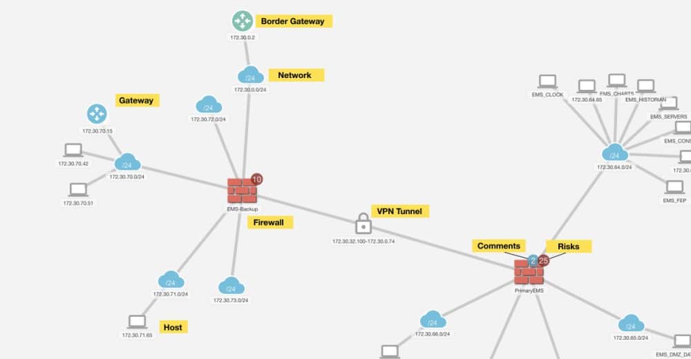
Based on your imported configurations, NP-View will create a map to connect and display nodes of the following types:
- Firewalls (physical and virtual)
- Routers (physical and virtual)
- Switches
- Host-Routers
- Networks (subnets)
- Hosts
- Gateways
- Border Gateways
- VPN Tunnels
- Unmapped Hosts and Networks

Details: Each node is represented by its own individual icon on the map, and when clicked will open a details panel with information about the selected node. From each details panel devices can be assigned a category (colored text tag) and criticality (colored ring).
Risk Display: If a device has active alerts, the number of alerts will be displayed as a red circle on the device icon.
Unmapped Gateway:
- Unmapped hosts and networks indicate IP addresses that are external to the topology and could not be connected to primary networks.
- For a given networking device (e.g., a firewall), primary networks constitute the IP ranges defined by its interfaces.
- In other words, all the networks a device faces are called primary.
- Nonetheless, the device’s ruleset can refer to arbitrary IP spaces, not necessarily those within primary ranges.
- Consequently, NP-View identifies those external/unknown IP spaces as hosts, networks, or ranges, as defined in the config, and places them behind the Unmapped gateway.
Organizing the Map
On the Topology Map, users can rearrange any object or group of objects on the canvas by simply selecting and dragging a device to a new location. Device locations can be saved with the “Save Topology” button which can be found in the top center of the screen.
- Multiple devices can be selected by holding the shift key down (the cursor changes to a + sign) and dragging the mouse to make the selection.
- The Ctrl key can be used to select / deselect individual devices.
- Once selected, the devices can be assigned to a common category or criticality.
- Alternatively, the devices can be segmented into zones. See more info on zone creation.
Save Topology: When objects are moved on the topology map, the ‘Save Topology’ button will become active. Multiple objects can be moved prior to saving the topology.
If the user attempts to switch views before saving, a notification will be presented as follows:
The user can proceed to the selected view without saving by clicking “OK”, or they can choose “cancel” to go back and ‘Save Topology’ .
Other Topology Functions
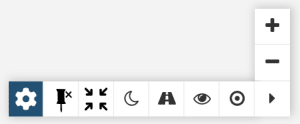
Settings: Opens a panel with user preferences that can be set for the map. See the section below for more
Pin/ Unpin Topology: Selecting this, moving one device will cause the map to auto arrange. This can be helpful if when importing a large number of devices, the topology map initially displays with overlapping devices
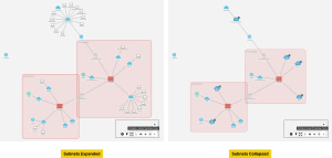
Collapse/ Expand Topology Nodes: Some Topology Maps may become visually overwhelming depending on how many nodes are present. This setting will hide end points and only display Primary devices and networks
Night Mode: Sets the map to a different color scheme
Highlight Paths: Opens the Highlight Paths menu item. See the Paths article for more.
Manage Views: Opens the Manage Views menu item. See the Manage Views article for more.
Center Map: Centers the map on the screen
Topology Settings
NP-View provides a settings menu specifically for the topology. This menu can be used to show as much or as little information as you desire on the topology map. This keeps the topology map at a level of organization that suits your use.
The topology settings menu is easily accessible from the menu in the bottom right of the topology map by clicking on the gear icon.
This will open the topology settings dialog and allow users to show or hide different types of information on the fly.
- Show/Hide Vulnerability Shields – this setting toggles the display of icons that show vulnerabilities on nodes when scans have been imported into the workspace.
- Show Networks with NO IP – this setting toggles the display of networks / interfaces (white cloud icons) that are defined but have no IP address assigned. The default behavior is to hide them.
- Show Only Bridge Groups
- Show Risk Bubbles – this setting toggles the display of the red bubble on Primary Devices that indicates the number of risks associated with that device.
- Collapse Nodes By Default – this setting toggles the behavior of whether or not nodes on the topology map are collapsed.


